Air Conditioning
The AC controls are shown below, as well as an explanation of their functions. When correctly setup, the AC trigger button will cause the engines idle to raise slightly (Ramp Up), and then stabilize as the compressor comes in. It is usual for an AC system to have a pressure switch inline before the Switch Input to the ECU, such that the compressor will turn on and off as system operates based on its own pressure.
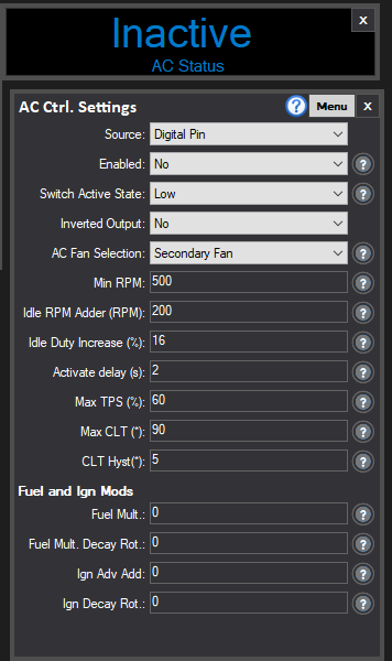
Source
If set to a digital pin, it is the input assigned to "AC Switch" in the Input Settings.
Enabled
Enable/Disable the AC Algorithms,
Switch Active State
State when the AC is considered active for the input.
Inverted Output
Whether to drive the Channel "on" when AC should be ON, or, should we invert it?
AC Fan Selection
Choose which is the AC Fan (None, Primary Fan, Secondary Fan, or Both Fans) - as assigned in the Output Settings.
Min RPM
The minimum RPM before we start to asses AC requirements
Idle RPM Adder (RPM)
If using a closed loop Idle strategy, the amount higher than the target table we should add in terms of RPM.
Idle Duty Increase (%)
An immediate Idle Duty percentage driver increase amount to compensate for additional load on the engine.
Activate Delay
Once the AC Switch input is triggered, a timer starts. At the time entered here (seconds) the compressor (assigned by 'AC Relay' in IO Settings) and fan (if set) then activate. THis lets the engine settle to its new commanded higher RPM before the load comes in. During this delay period, the AC Status DRO will show "Ramp Up".
Max TPS/CLT
The maximum throttle percent and coolant temperature to allow AC to work. Above this, AC will either not operate, or turn off.
Fuel and Ignition Modifiers
To compensate for the extra spike load, you can set ignition to advance and fuel enrichment. These enrichments will decay over the number of engine rotations specified accordingly.