Coil Outputs
The ME ECU range has two types of coil outputs, either Active/TTL (Transistor Transistor Logic) or Passive/IGBT (Insulated Gate Bipolar Transistor). You need to make sure you use the right kind of output for the coils you choose to use, or vice-versa. The Plug-In range has the correct hardware type (either IGBT or TTL) to suit the OEM ignition system, as well as the correct settings when you load a suitable base map.
Both types are explained here:
TTL "Active" Coils & COPS
TTL coils usually have an ignition amplifier built in, and expect a simple 5v signal from the ECU to tell them when to dwell (to start charging the coil) and when to fire. Most TTL coils work on a positive or "normal" logic mode. That is, 0v on the signal pin and nothing happens, and when 5v is placed onto the signal pin the coil beings to charge, then, when the signal pin goes back to 0v, the coil then fires.
TTL coils usually have three or more connections as they have an ignition switched power (12v) a ground and a signal wire at a minimum.
For more information on wiring COPs please see here.
IGBT "Passive" Coils
IGBT (sometime called dumb/passive coils) are simply a wire wound transformer. They typically flow several amps, and as a result require an IGBT (high current ground switch) to drive them, as fitted to our ME442 and ME221 wire-in ECUs. The ECU provides a connection to earth, with the other side of the coil being connected to a fused ignition supply. When the ECU wants the coil to fire, it connects it to ground, allowing energy to flow through the coil, and then, and the right time, it breaks this connection causing the coil to fire.
IGBT (or "dumb") coils usually have only 2 connections per coil channel as they are simply a coil of wire within. They will have a 12v ignition switched supply to one connection, and the other will run to the ECU which is switched to ground via the high current IGBT driver, allowing current to flow, and the coil to "charge" or dwell.
Most Japanese models use TTL coils and a module - as a result most of our Plug-Ins are set-up for this, offering a simple 5v output for the coil trigger lines.
The ME442 Wire-In offers 8 ignition/coil channels, and these can be set to either TTL or IGBT mode from within MEITE. (In the Ignition Driver)
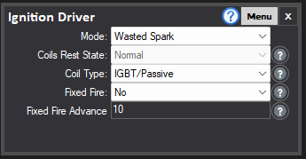
The ME100/ME221 GEN1 Wire-In offers 2x IGBT channels. Suitable for directly firing standard coils such as Ford Coil-packs.
The ME221 GEN1 has two IGBT coil drivers built in, so direct driving of wasted spark coil packs is the common method of ignition control. In this mode, be sure to set ignition drive mode to ‘normal’, not ‘inverted’, as this may cause damage to the ECU. COIL.1 and COIL.2 are the respective outputs for the ignition coil. Generally, the coil receives a 12V ignition feed (we recommend fusing at 10A), and the coils -ve terminals run to the ECU. COIL.1 generally ignites the spark plugs for cylinders 1 & 4, while COIL.2 operates the spark plugs for cylinders 2 & 3 (as set by the Ignition Driver). A typical ‘Ford Type’ coil pack and its pinout is shown below.
The GEN2 Range of Wire Ins have 4,6 or 8 coil outputs depending on if it is the ME221, ME360 or ME442 variant.