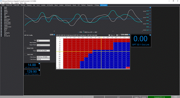
GPT Example 1: AFR / Load Safety Cut (Failsafe)
A typical use of a GPT may be to protect an engine., If the user connects a wideband sensor to the ECU, and has properly calibrated it, then the ECU will also report the “Wideband AFR”
We may want to protect the engine from running outside of these parameters - if we detect a lean AFR when a turbocharged engine is on boost, this would be a catastrophe, and it would be best to cut the engines power at this point.
We cannot simply use the Wideband AFR Error to act upon, as in some circumstances, such as cold idle, overrun and startup, the AFR error from the target table will be not repeatable.
A simple GPT set-up for this would therefore require a two-dimensional table, that outputs a fuel trim (perhaps a slight en-richening in “slight” circumstances, with an overall fuel cut if the engine goes outside of parameters.
We would implement this like so:
First we need to capture the data we wish to use in designing this fail-safe control:
- Create a New Blank Tab using the View>Layout Manager menu, and name it “AFR Failsafe”.
- Add to the tab Wideband AFR, MAP and RPM histograms.
- Carry out power runs (assuming the engine is safe) noting AFRs seen under different levels of boost and RPM - this is the baseline “safety” level as a tuner you don’t want the engine to operate outside of. Note you can press the key “P” on the DRO Histogram to pause the data after runs and use the cursor to review the acceptable AFR at given MAP levels and RPMs. You can skip this step if you already have an idea of safety targets in mind.
Next, we create the GPT control strategy. We don’t have any other GPT algorithms setup, so we will be using GPT 3D 1 for our control.
- Add to the tab: (Under GPTs) GPT 3D 1 Config, GPT 3D 1 Out Link, and the GPT 3D 1 table:
- As this table type will be outputting “Data” as opposed to a direct PWM output, its type should be set to Data in the config window.
- As we will be affecting the fuelling output, its Output should be changed to “Safety Cut”
- X Axis Source should be set to “Lambda/WBO2 Cur AFR [900]” and then set the Y axis Source to “MAP [6]”
Next we need to set the the actual GPT 3D table up. Remember we have assigned the output to use the Safety Cut trigger. Any number other than ZERO fed into this module will cut the ignition events from happening. This because as it moves between two fields or 0 and 1, the system will interpolate to deliver 0.5 etc, and what we require is a hard cut based on leaving the acceptable cells.
First we will setup the Axis. The top (X-Axis) we defined to be sourced from “Lambda/WBO2 Curr AFR” - so the current AFR is used to look up the left-right location of the output. We will fill this top row evenly from 10-18 AFR by double clicking each top item and changing it as such.
The Left (Y) axis, we defined to be supplied by “MAP” - (manifold pressure), so we will scale this from 0(vacuum) to 300kpa which is 2 bar of boost, as 1 bar (100 kpa) is atmospheric pressure.
The cells we will fill out as we see fit as a tuner, for example AFRs over 14 when above 150kPA should result in complete safety cut to save the engine. The end result of this strategy is shown below: