GPT Example 2: Shift Light
In this example we will set up a single LED shift light which will activate at a certain RPM. It will flash as we approach the shift point (7000rpm), then light solid at the limiter (7300rpm).
Source a 12V automotive High brightness LED. (These have the built in current limiting resistor). Wire it to a spare PWM Low Side Driver as shown below. Note it must be wired the correct way round to function. The positive is usually a Red Wire.

Now we must configure the General Purpose Table to operate it.
First create a new tab using the layout manager, named 'Shift Light'.
Add to the tab:
- Inputs>RPM
- GPTs>GPT 2D 1 Inp Link
- GPTs>GPT 2D 1 Config
- GPTs>GPT 2D 1
The display will now look like the below:
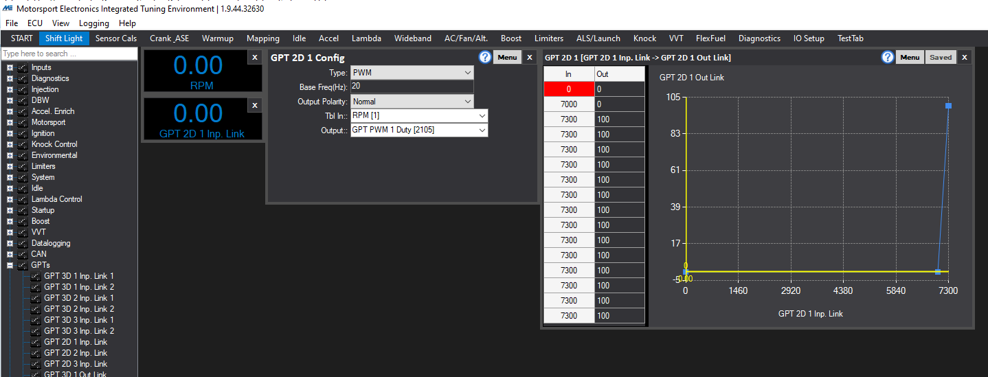
Configure as per the above image, Note we have set the output to be a "PWM" type, with a Base frequency of 20 Hz. (So when the Duty is 50% it will flash On and Off 10 times a second, half of 20). Polarity is Normal, so 0% Duty = the LED of OFF and 100% means it is on. And we have set the input for the 2D Table 1 to be RPM and its output to go to the GPT PWM 1 Duty place holder.
Next we edit the GPT 2D 1 Table such that below 7000 RPM the LED is OFF and then as we approach 7300 it goes from fully off to fully on. Then we fill the rest of the table such that there are no random numbers anywhere.
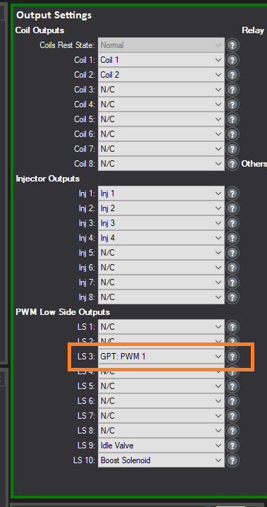
The final step is to assign the output. We have chosen to wire the LED in this example to Low Side, or LS, number 3, so under the IO Settings/Output settings we set LS3 to be GPT PWM 1, as shown below.