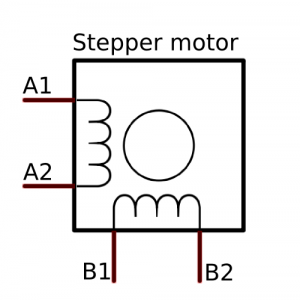
Stepper Idle Motors
There are two-types of Stepper Idle Motor in use - four (bipolar) wire and six (unipolar) wire.
Only certain versions of the ME range support four wire, while all version support six wire. For four wire support the ECU Must either be a Dual Drive-by-Wire version of the ME442 or, the ME360 with Stepper Idle Control.
For six wire, two of the wires (in below diagram they would be AC and BC) are an ignition switched 12V supply. Below is a typical wiring guide for any of our ECUs. Be sure to use normal, high current Low Sides, and not "Relay Low Sides" for driving stepper motors.
The other I/O mappings on the Low sides would be, for example, as following:
- A1 -> LS1 - Set to "Stepper 1"
- A2 -> LS2 - Set to "Stepper 2"
- B1 -> LS3 - Set to "Stepper 3"
- B2 -> LS4 - Set to "Stepper 4"
You may use different Low Sides, but it is important that Stepper 1+2 go to one "phase" and Stepper 3+4 go to the other phase. The website here gives a good description on how to work out which phase is which.

For the less common, four wire, bipolar steppers, you would wire then to the stepper outputs on the ME ECU as per the diagram - the earlier ME442 Wire-Ins use H Bridge A & B.
- A1 -> "Stepper 1" and set to "Stepper 1"
- A2 -> "Stepper 2" and set to "Stepper 2"
- B1 -> "Stepper 3" and set to "Stepper 3"
- B2 -> "Stepper 4" and set to "Stepper 4"