Testing Throttle Operation
Once you have succesfully calibrated the PPS and TPS sensors in your DBW instalaltion, the next step is to test the actuation of the throttle motor.
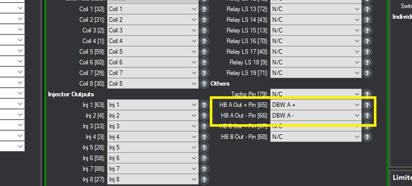
Be sure to have the H-Bridge outputs set to use DBW A if you are working with just one DBW setup, and wired to the pins as specified. YOu can do this in the IO Settings (Output Settings) as shown below:
You can now head back to the DBW settings, and start a manual test mode.
First, have the following items on display, as per the standard DBW layout show below:
Be sure to set your Solenoid Base Freq. to that specified by your DBW motor supplier, usually 500-1000Hz is typical.
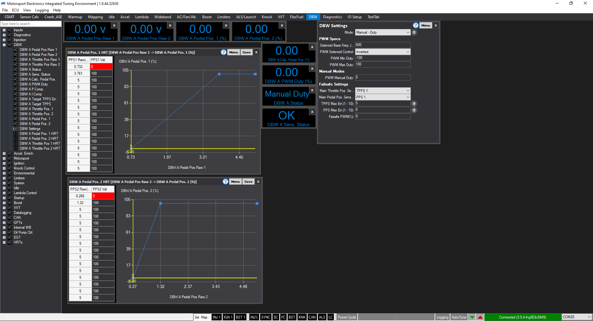
Next, set the DBW Mode to "Manual - Duty".
You can now try entering a duty into the PWM Manual Duty box (try -30 to 30-40%) and you should note the throttle plate will move. If it does not check, that the Duty is indeed what you have typed in, and then check wiring. If you find that the throttle opens with a negative duty (i.e. -40%) then you should change the PWM Solenoid Control from Normal/Inverted as necessary such that a high duty (say 80%) drives the throttle open, and a NEGATIVE duty (such as -50%) drives it closed.
The next step is to test "Manual - Position". You can then enter a target position % for the throttle plate, and it should meet it.
This confirms the throttle motor is correctly wired, and that its frequency and drive direction is also correctly set.
The next step is to set it to track the pedal position (by setting the correct mode and fail-safes) and then tuning its PID so it tracks quickly without overshooting.