Trigger Routing
The ME platform has the ability to allow the user to select different pins to be used for trigger inputs. This is used only in wire-in applications generally. Plug-Ins should use the settings configured as part of the standard base-maps.
Use the information in the wiring section on how to use either type.
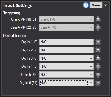
Below you can see the trigger routing box as part of the Digital Input settings. Note that VR inputs are specific to VR sensors, while Digital Inputs can only accept Hall sensors (or other digitial sensors.)
You would select for each pin the signal that is going into it, as below you can see that the VR Crank (pins 80, 81)and VR CAM A (pins 22 and 23) on the ME442 have indeed been assigned to expect the signals from those sensors.
The second example below shows how we may use a VR Crank sensor (and therefore wire it to VR Crank), Cam A VR for the Inlet Cam, and use DIG IN 2 pin as an input for the engines hall-effect Cam Sensor on the exhaust cam (Cam B).
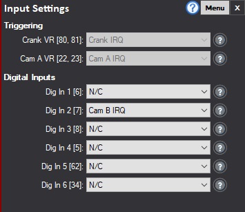
You can test that the signals are routed correctly by checking for increasing IRQs when cranking the engine.