VTEC / Switched VCT Mode
The VTEC system of the ME221/ME442 allows a band gap system of Load and RPM. It will also switch to the secondary Fuel and Ignition tables during VTEC operation to compensate for the different engine characteristics.
The VTEC switching system is defined by six data points. These can be found in the VVT Settings under VVT. Be sure to set the VVT Mode to "Sw. VCT".
You can also set the fuel/ignition tables to switch to the second maps (useful for accurate fuel/spark timing when in the higher lift modes) by setting the source as "VVT Active" under System>Map Sel. Settings, and choosing which tables to enable switching. Then, when the VTEC is active, the secondary fuel/ignition tables will be used.
The diagram below illustrates how the VTEC enabled zone is configured. When the parameters of LOAD and RPM are in the Green zone, then the VTEC output (VVT Cam Advance A in IO settings, on your chosen LowSide output) will be to ON (ie GROUNDed). When outside of this zone, it will be turned off.
Also, note that minimum coolant, throttle and vehicle speed (VSS) also need to be met for VCT to be activated.
There is also an RPM and Load hysteresis which will stop repeat triggering when at the threshold points.
PWM params and Manual Mode settings are ignore when in "Sw VCT"/VTEC mode.
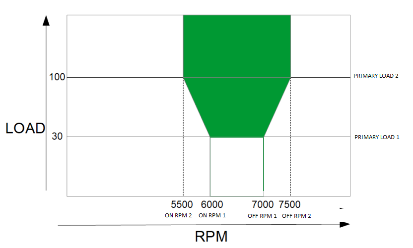
The above diagram, when set in the VVT Settings, would appear as below:
