


A Coil-on-Plug (COP) upgrade adds a nice look to the engine bay and unlocks the option for fully sequential ignition i.e. where each coil is controlled and triggered individually by the ECU. This can be useful when higher dwell times are needed due to higher boost levels. It usually becomes a required modification for engine builds with a target power of 300bhp and above. This gives the option to deliver a bigger or higher energy spark for those high-power, boosted builds that the stock coils cannot handle.
This article relates only to the Gen2 (White) MX-5 ME221/ME442 Plug-in ECUs, though much of the information would be useful for Gen2 plug-ins for other models.
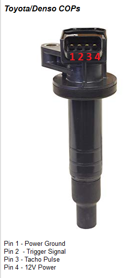
There are a couple of options to choose from when selecting a particular Coil-on-Plug setup. Most customers tend to use either the Toyota Denso coils or the more powerful VAG/Audi COP units.
The images below should help you identify these two main types and highlight the differences in pin-outs/wiring involved.
Note the VAG Coils are the “long/normal” type. The “Short” style have a different pinout.

Next, we will cover where to connect these wires dependent on your model/year of Mazda MX5. In all model years of MX-5, COIL 3 and COIL 4 trigger signals come out of the AUX Plug on the Plug-Ins baseboard.
COIL 1 and COIL 2 should be triggered by the stock ignition trigger pins on the main ECU header connector. Details of where to obtain these signals is detailed below for each model year:
The ground wires should be of heavy gauge wiring and they should be neatly grounded to the cylinder head. Failure to do so can create electrical noise which has the potential to affect USB operations of the ECU.
Comprehensive wiring diagrams and test information is shown below, should you wish to create a small sub-loom for the install.


Software Setup (MEITE)
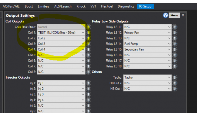
Once you have installed the COPs, the next step is to test they are working as they should. Connect up in MEITE and in the Output Settings of the IO Setup tab ensure that COIL 1-4 are set to Coil 1 – 4 in the relevant drop-down menus (you will likely need to assign coil 3 and coil 4), If this table is not visible, it can be found under the ‘system’ menu of the tree view on the left-hand side of MEITE. Double click to open it.
Next use “TEST: INJ/COIL” for each COIL (1-4) one at a time and check that a plug fitted into the end of the COP being tested (with the spark plug collar resting against the cylinder head) spark/buzzes. Do not do this for a prolonged period of time as you may damage the COP unit. A quick few seconds is all that will be needed. Assign it back to the relevant coil number (1/2/3/4) after each individual test is complete using the drop-down menu. Caution should be taken as usual when working with spark plugs due to the risk of shock from HT equipment.
You can see the MEITE setting below being used to test COIL 1:
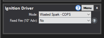
After you have completed the test, the next step is to get the engine running on the new setup. Set the Ignition Driver Mode (found under the START tab) to ‘Wasted Spark – COPS’ in order to initially test run the engine using the four individual coil trigger outputs from the ECU but in a wasted spark setup.
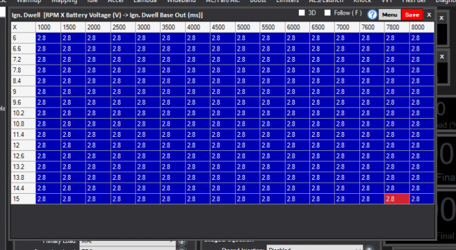
Also, set the Ignition Dwell table (under ‘ignition’ to all be at 2.8ms (check with your coil supplier/tuner for the actually preferred setting but this is a rough and ready “safe” dwell table.) To edit cells just highlight them and press backspace. Type the new dwell time and press enter. Click the red save button in the top right-hand corner when finished.
Once this is done, switch the ignition off for a few seconds and then back on. Crank the engine, applying throttle if needed for startup. If the test mode passed (confirming the wiring was right) the engine should start and run as it did on the OEM coils. Great!
The next step is to enable a fully sequential operation. Go back to the ignition driver and now set Ignition to Fully Sequential.
Switch ignition off and then back on to ensure all changes have been applied, then attempt to start the engine. If the engine fails to start, then do not worry as there is usually a quick fix. The most likely cause is that the phasing of the ignition is 360 degrees out. To correct this, add 360 (or subtract 360 if the Trigger Offset is already larger than 360) from the number, press enter, and retry. You can find the Trigger Offset number in the Engine Driver under System, and the box should change colour to green once you have pressed enter, indicating that the change has been accepted.. eg If your trigger offset is 214, you cannot remove 360 as this would make the number negative, so add 360 degrees giving 574 degrees. Alternatively, if your trigger offset is 545 then you should remove 360 degrees, so your final offset angle would be 185.
Try starting the engine. You should now have a running engine on COPs, in fully sequential mode!


